Project Opticam
The Idea: To install a small digital video camera in a rocket which can capture the entire flight. I was inspired by an article in the May/June 2002 edition of Sport Rocketry entitled "Getting Started in Video Rocketry", and have always wanted to record a rocket in flight. This is an idea that has been intriguing to model rocketeers for decades. The first successful video rocket was launched back in 1962 by Paul C. Hans and Don Scott of Port Washington, NY.¹
Opticam Flight 1, First prototype,
|
Opticam Flight 2, First prototype,
|
Opticam Flight 3, Second prototype
|
Building the Rocket
Choosing the right rocket for the job was important in this project because the camera will be situated in the nose cone, moving the Center of Gravity forward. To offset this potential problem, two things were necessary: 1. The rocket would need to be fairly long, and 2. The rocket would need to have larger fins to help stabilize the heavy payload.
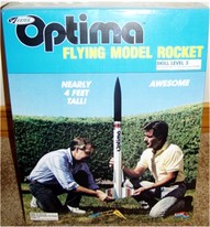
Since I gravitate toward building out-of-production kits, I chose the Estes Optima which was produced from 1990-1994. This kit is 2.5" in diameter, has a large fin span, and is about 4 feet in length. Not to mention it has a retro look which I think is pretty cool. While this rocket worked great to test out this project, it became obvious after the second flight that the fragile airframe would never boost this camera to the heights I wanted to achieve. Enter the Opticam 2, using the classic Loc Precision High Tech H45 rocket. Since the camera unit was designed to fit in the nose cone, this makes it easy to use with various rocket designs. The Loc kit offers a more durable airframe which can take a 38 MM motor, making it possible to achieve the 2000 foot flight I'm hoping for. Building both kits was straight forward, and no modifications other than replacing the cheap Estes plastic chute with a respectable nylon chute were necessary. For the Loc kit, I reinforced the fins where they join the motor mount with 30 minute epoxy for maximum strength.
Since I gravitate toward building out-of-production kits, I chose the Estes Optima which was produced from 1990-1994. This kit is 2.5" in diameter, has a large fin span, and is about 4 feet in length. Not to mention it has a retro look which I think is pretty cool. While this rocket worked great to test out this project, it became obvious after the second flight that the fragile airframe would never boost this camera to the heights I wanted to achieve. Enter the Opticam 2, using the classic Loc Precision High Tech H45 rocket. Since the camera unit was designed to fit in the nose cone, this makes it easy to use with various rocket designs. The Loc kit offers a more durable airframe which can take a 38 MM motor, making it possible to achieve the 2000 foot flight I'm hoping for. Building both kits was straight forward, and no modifications other than replacing the cheap Estes plastic chute with a respectable nylon chute were necessary. For the Loc kit, I reinforced the fins where they join the motor mount with 30 minute epoxy for maximum strength.
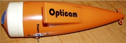
Building the Camera Unit
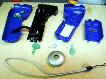
With all of today's technology, there were actually lots of choices for what kind of video camera to choose, however, the two main considerations for me were quality and weight. When it came down to it, the Intel Digital Movie Creator was the best quality unit, based on it's small size. Just as was disovered by Jamie Clay in his Video Rocketry article (Sport Rocketry), the other cameras thus far just don't cut it. This camera is also out-of-production now, although can still be found for around $75.00 online. The first step was to strip this camera of dead weight. The plastic body comes off this camera quite easily by removing a screw, and using a screwdriver to pry the two halves apart. Once inside, you will see a metal shroud protecting the board. I decided to strip this board down to the bare essentials, so this had to be removed by de-soldering the two halves.
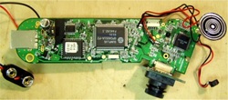
Once you have removed the metal shroud, the next order of business is to remove the battery tray/lens assembly. This can be achieved by de-soldering (carefully) the two prongs for the battery case from the back of the board. Take note of these connections on the board as you will need to solder your battery connection here. I converted this to 9 volts to save space and provide a more reliable power connection. I also installed a switch to shut down power to the camera and to be able to wipe the memory clean since some of the features won't be accessible now that the buttons have been removed from the board. Another important note before getting too far along, is to set the camera at the film quality you want as you won't be able to get to this feature after stripping the board and installing in the nose. Note in the picture of the board the battery wiring, the mic and speaker have their place in this design later, just be careful of them. After you have the board completely stripped, and the 9 volt battery supply soldered, you can focus your attention on wiring the camera switch. This was probably the trickiest part of this conversion. You will see the switch on the board that activates the camera, take note of where this switch meets the board, on either side you will see the connection for the switch. Solder two long wire leads (trim later) to the connections just mentioned, and you will be ready to install your switch for the camera later. As you will see in my completed Opticam, I used a toggle switch for this application.
Finishing the Camera, Nose Cone Unit
After all your soldering on the board is done, you can move on to designing the nose cone. The only practical way to use this camera is with a mirror, given the shape, and how it will fit in the nose cone. The only disadvantage of the mirror is that your images will be reversed. You should begin by cutting the collar of the nose cone in order to gain access to the inside of the nose. Next, you should fix your anchor points in the nose cone and reinforce with epoxy, be generous. If you want to capture footage during descent, you will need to have anchor(s) in the tip of the nose. Next you will need to determine where the opening for the camera will be located. Remember to design your camera so the port on the bottom is easily accessible from the bottom of the nose cone (see pic) when measuring your cut-out. After you have your cut-out for the camera, you should shape some 1/16" balsa around the inside of the nose cone collar you cut so it can slide back in place later. I found using epoxy to keep the balsa in place worked well, a piece of masking tape will hold the bottom of the nose cone collar in place for final assembly. The picture on the left shows the masking tape holding the collar together. Next you will use 1/4" balsa stock to form a cradle inside of the nose cone that will hold your camera in place. Use the unique shape of the board to assist you in preventing movement when building the cradle. I placed a piece of balsa on the cradle that fit in a groove on the board which locked it into place nicely. After you have the bottom of the cradle built and are satisfied with how the camera sticks out of the nose cone, remove.
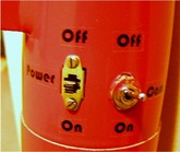
Now you can drill holes for your switch placement, see the picture that shows my switch layout. Next, place the camera board in the cradle, and get all your wiring and switches in place. Finish the top of the cradle for the camera board. I placed the battery on one side of the board with a shelf below it and foam around everything. Now you can build up your hood, first by cutting the two uprights. I found a mirror from a local craft shop which is 3/4" X 1 1/2" and works nicely. You should prepare the mirror by gluing to a piece of balsa stock the same size, making a backing which will aide in fixing the mirror to the hood. After the mirror is prepared, get your uprights glued in-line with the nose, positioned over your camera lens opening, and a width equal to the mirror width. Once you are to this point, the next step, adjusting your field of view needs to be done with the camera plugged into your computer. Bring your CA with you to your computer station, and adjust the mirror in the opening until you are satisfied with your view, CA in place. I used a drop of CA to position the mic inside the hood and keep it in place. The speaker was glued to the inside of the nose cone, where holes were drilled in a pattern to allow the audible noises from the speaker to be easily heard. After some finishing, painting, and final touches, your modular camera nose cone is complete!
Flying Opticam
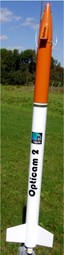
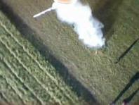
Flying the Opticam: The maiden voyage of my Opticam was less than I hoped for. The motor, an Aerotech E15-4, was too little for this rocket, and as you can see in the first video, it quickly tipped over and headed for what appeared to be it's last flight as well. Fortunately, the ground broke the fall of the camera :-) Which also tested the durability of this design. It was ready to fly again with only minor scratches to the paint. The next flight on an Aerotech E30-4 was just the ticket. You can see in the video of this flight how straight it flew, perfect flight! Recovery system deployed at apogee. Finally, everything went as planned, and some great video footage of the event makes a great trophy. The most recent flight was on an Aerotech G35-7. A perfect flight, this motor really sent the rocket off the pad in quick time. Recovery deployed at apogee again, and some amazing footage frozen in time. Estimated height of this flight was about 1200 feet using wRASP. For future flights, I will use an altimeter to determine actual height. Summary: This was my most rewarding rocketry experience, and I would recommend this to any rocketeer. I have to continue improving the recovery system to reduce the spinning on descent, but overall was pleased with this project. Soon the Opticam will launch with an H238T which should get it close to the 2000 foot mark I'm looking for.
1 Information from G. Harry Stine's Handbook of Model Rocketry, sixth edition
1 Information from G. Harry Stine's Handbook of Model Rocketry, sixth edition
